
Space-E/CAM

An intelligent CAD/CAM system that supports a high-efficiency machining function and automatic path creation with an easy operation
- Functions
- Options
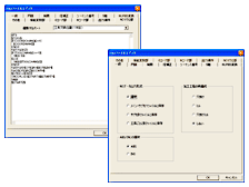
Machining process design supports automation and standardization of machining data creation. This design has the mechanism enabling accumulation of customers' machining know-how such as various palettes and templates. You can perform an easy operation to create NC data.
Create Path
Roughing
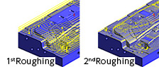
Roughing consider the stock model cut by previous process.
It enables to create more efficient cutting path to cut the rest of material.
Contour Rest Cutting

Create semi rough path applied to the rest of material after rough process.
Previous tool can apply ball and radius type.
Contour Finishing
Create path automatically to unfinished area such as gentle slope area.
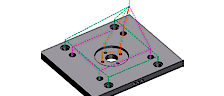
Free Path
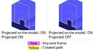
Because any wire frame shapes can be converted to paths, paths for line-carving machining can be created.
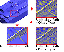
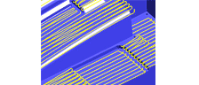
Parallel Finishing
A machining path of an image can be created, following any direction.
A path vertical to a scan line direction is automatically added to an unfinished part. In addition, you can also specify cutting directions such as rushing up and following down.
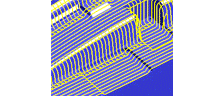
Flat Part
When an angle for recognizing a flat part is specified (its range can be specified), a scan line path is automatically created only in the range.
This machining function produces the effect on the flat shape that cannot be effectively finished in contour machining.
Edit Path
Path Editor
Path Editor is implemented to edit cutting path.
There are following edit functions.
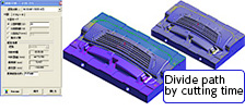
-Join, Divide
-Divide by cutting time, cutting length, cutting height
-Edit Approach, Edit Pick, Extend Section
Cutting Simulation
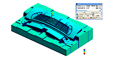
Compare design model and cut model, and display color map depend on volume of rest material.
Green : design and cut model is same
Blue : Rest material
Red : Gauge
Cutting Simulation function can show the following result.
-G00 interference
-Interference of shank and holder
-Check effective tool length
-Specify rest material by comparison design model and cut mode
- Comparison with a model shape -
A map is displayed by color according to the volume of rest materials. Based on the results of comparing a model shape with a cut shape, parts having the same shape are displayed in green. Parts having the larger volume of rest materials are displayed in a cold color. Parts having the larger volume of cut materials are displayed in a warm color.
Path Optimization
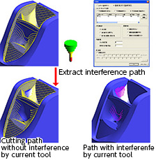
Divide at shank and holder interference. Remove or extract shank and holder interference.
It enables to cut a part as much as possible by current tool.
High Speed Cutting
Incorner R
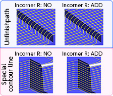
Insert R shape at corner in order to prevent feed rate reducing and gauge at corner.
3D Arc Approach
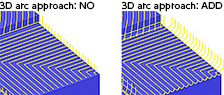
Add 3D arc approach to reduce tool load.
Other Functions
CAMWEB
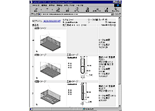
Cutting Order Sheet is automatically created in HTML or Excel format.
Customer can design own sheet format.
WIRE EDM
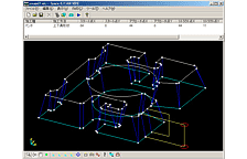
Easy to create wire EDM data by 3D graphics.
Functions required for wires are well equipped, such as a vertically deformed shape and corner processing.
DRILLING
Support fixed cycle drilling data for mold base application.
Because drilling can be used in process design, data can be processed in combination with other 2D machining functions.
Postprocessor
Postprocessor provides abundant parameters to support optimal machining, an NC code definition function flexible to a used machine tool, and a strong macro function that can define each and every word of NC data.
By using a special wizard and editor, customers can easily create and edit data by themselves.
Tool Database
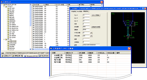
Database of various tool makers are provided as standard equipment.
The database also includes cutting conditions provided by tool makers (a feed rate, rotation rate, and cutting amount).
Cutting conditions recommended by the tool manufacturers can also be imported.
![]()